Demo Topic: Diagnostic Pacing
| Site: | Micropace eLearning Portal |
| Course: | Demo |
| Book: | Demo Topic: Diagnostic Pacing |
| Printed by: | Guest user |
| Date: | Saturday, May 4, 2024, 6:17 PM |
Description
The concept of electrophysiology was first recognised in the 1960’s, followed by diagnostic simulation in the 1970’s and finally RFA in the 1980’s (Boyle, 2002). This section explains the main protocols and their uses: to induce, to measure, or to terminate a tachycardia.
From this point forward it is assumed that all students are familiar with the common pacing terminology explained in Pacing 1 – Fundamentals (such as “S1”, burst, BPM conversion to milliseconds, etc).
1. Protocols for EP Measurements
Train pacing (or "S1 trains")
This type of pacing is considered the simplest pacing protocol, it usually consists in delivering several pulses at a fixed rate during certain amount of time. It is normally used to test the automaticity of a node or focus. In most cases, this is achieved pacing at an slightly higher rate than the tested node or focus, then stopped and observing the later response (jumps, pauses, possible tachycardias, etc.).
The most extended use is to measure the Sinus Node Recovery Time (SNRT) at the beginning of a normal EP study. Generally, we will pace from the atrium close to the node for 30-40 seconds repeatedly (with cycle lengths of between 700ms and 300ms). After every, pacing cycle we will measure the time that the sinus node takes until recovers its normal activity.
Used for:
- Sinus Node Recovery Times
- Arrhythmia induction
- Termination of arrhythmia
- Entrainment of arrhythmias

Decremental pacing for Wenckebach periodicity
This is a routine part of the EP study, to assess the conduction from Atrium to Ventricle or from Ventricle to Atrium.
A train of S1 pacing is delivered starting at the patient`s intrinsic cycle length, and then gradually shortening the cycle length of the pacing stimulus (decrementing) every approx. 5 beats. For each stimulus delivered into the atrium, a resultant beat should occur in the ventricle (likewise from V to A).
Eventually the pacing will be delivered so fast that the AV node will not be able to keep up, and a degree of delay will slow the impulse (nodal delay).
Finally a beat will be dropped. The paced cycle length at which this occurs is termed the AV or VA Wenckebach respectively. It is important to check that if a beat appears not to conduct to the ventricle, that the atrium was in fact captured.
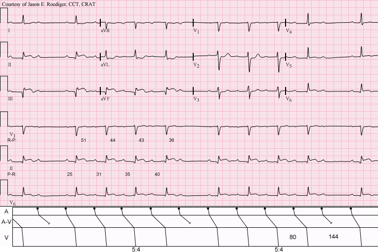
(Above) Sinus rhythm with acute inferior infarction complicated by Type I A-V block manifest in the form of 5:4 Wenckebach periods; R-P/P-R reciprocity. [Pic1]
If the terminology ‘Incremental’ and ‘Decremental’ is still unclear:

Refractory Periods Measurements (AV Node)
Extrastimulus testing in the AV Node is another routine component of the EP study, another aliases for this part of the study are: Single extras, AV Nodal Curve or AV Nodal Refractory periods.
An extra-stimuli with a conditioning train for induction of re-entrant tachycardias and refractory measurement of the AV Node.
Method:
The purpose of the 8 fixed conditioning beats is to establish reproducible cardiac conduction velocities, so the isolated effect of the varying S2 can be observed. The AV node will cause delay in the extra stimulus at shorter coupling intervals, and eventually block an early S2. When this occurs, the S1-S2 interval is termed the effective refractory period of the AV node (AVERP). Before block occurs, if enough delay is induced, the retrograde limb of a tachycardia may recover, and a re-entrant arrhythmia induced (AVNRT or AVRT).
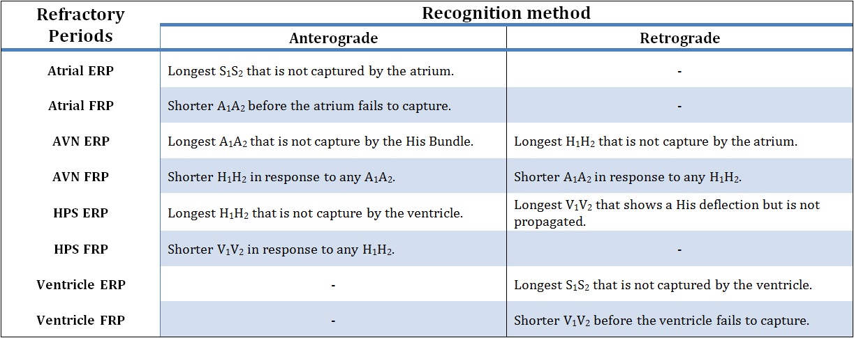
Above, possible definitions of Refractory Periods.
The extrastimulus is decreased routinely in some centers to below AVNERP until the extrastimulus fails to capture the atrium, or the Atrial ERP. This can be useful in some cases, as it may indicate myocardial conduction delay from intrinsic disease or the effect of drugs such as amiodarone or flecainide.
References:[Pic1] By Jer5150 (Own work) [CC-BY-SA-3.0 (http://creativecommons.org/licenses/by-sa/3.0)], via Wikimedia Commons.
2. Arryhthmia induction protocols
The induction of a tachycardia is in most cases the principal goal of pacing. The success of the induction depends on many factors such as: the stimulation location, the patient status, and of course, the mechanism of the tachycardia activation.
Rapid Burst pacing
Burst pacing can be used to trigger either re-entrant or focal triggered arrhythmias. When using Burst Pacing, it is recommended to deliver approx. 5-10 seconds of pacing at a time. The arrhythmia can be started at any point in the burst.
As arrhythmia induction using this method is based on probability, multiple attempts at varying cycle lengths are often required. For example, narrow complex tachycardias are typically induced by pacing slightly slower than the AV wenckebach rate, which is variable typically between 450 to 300ms. Atrial flutter is induced at faster rates between 300-220ms.
Inducing AF, for example in assessing WPW conduction, may be done with much faster pacing rates. Ensure that pacing is into the Atrium, as pacing rates faster than 200ms applied accidentally to the ventricle may cause VF.

 Warning!! Look carefully at ECG and make sure you see a sinus beat before restarting next burst pace. This is to make sure, in case you did succeed to induce the arrhythmia, that you don’t accidentally overdrive pace.
A common method of SVT induction is Pace at S1 just above Wenckebach rate. This method causes delay in the AV node, which allows retrograde pathway recovery, and re-entry. Select an atrial pacing catheter and use deliver S1 pacing at 10-30 longer than the AV Wenckebach cycle length.
If attempting to induce SVT, changing from HRA to CS catheter, which is closer to the re-entrant pathway may facilitate induction of arrhythmia. What could happen?

Single and multiple extra stimulus
This method of induction uses a single extra-stimulus to induce (usually) an SVT or a re-entrant tachycardia. The extra-stimulus may be placed after a number of sensed beats, but is usually placed after a paced train of eight (8) S1 stimuli, as this provides the most reproducible conduction characteristics.
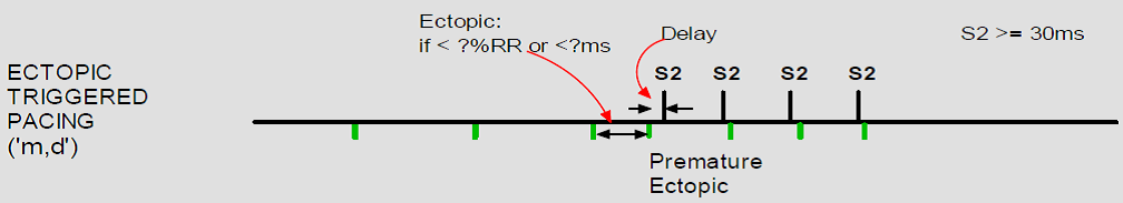
The 8 beat S1 train is used to regulate the subsequent refractory period, or single timed extras can be delivered alone following a sinus beat. This is the most physiological method of induction as it mimics a single ectopic which is what triggers arrhythmia in most patients. But as with clinical arrhythmias, induction is less predictable.

Short-long-short stimulation
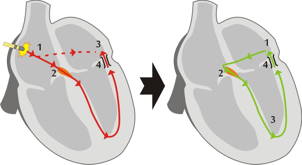
The induction of re-entrant arrhythmias requires that impulses travel round a circuit in one direction. In order to promote this, pacing aims to induce 'uni-directional' block, by maximizing the differences in conduction properties between the normal heart and a "pathway". The conduction velocity of an impulse in the myocardium is dependent upon the cycle length of the previous beat. Short-long-short stimulation uses a long coupling interval to lengthen the refractory period of myocardial tissue, making it more likely to block with the next short coupled extra which can conduct slowly into scar promoting re-entry.
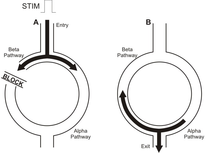
In the image above, we can a schematic representation of a re-entrant arrhythmia induction with extrastimulus. In diagram A, the pulse conducting through the Alpha pathway is blocked (in refractory period) meanwhile continues traveling through the Beta pathway. Later, in diagram B, when that pulse reaches again the Alpha pathway, this pathway has recovered so propagates the stimulus and starts the tachycardia.
Programmed ventricular stimulation
Ventricular tachycardia is usually induced by pacing using programmed ventricular stimulation.
The usual pattern (or Wellens protocol) consists in use 2 basic drive S1 cycle lengths (600 & 400ms). Following the conditioning train of 8 S1 beats, S2 is introduced from 300ms and decreased in 10ms intervals until it reaches refractoriness. Its timing is then fixed at 20ms above this point and an s3 introduced at 300ms which is then reduced in 10ms intervals. Further extra stimuli are delivered down to 200ms, at which point they are fixed and another extra added until 4 or 5 extras are used. The extra stimuli enhance differences between normal myocardium (where they increase conduction velocities) and scar (where they cause decremental type slowing). These conditions are ideal for the induction of re-entrant VT.
Pacing trains generally have a 3 second pause between repeat trains. Train repetition should not be interrupted if possible to maintain uniform condition of the myocardium.
Most physicians use up to 4 extrastimuli. Use of only 3 extra-stimuli may decrease sensitivity of the protocol (fail to induce VT in an existing pathological tachycardia circuit). The use of more than 4 extra-stimuli may induce clinically irrelevant tachycardias, especially VF.
To learn how to deal with common problems using extrastimuli to stimulate the ventricle:

 If you are using a Micropace Stimulator and you want to pace S1 into A & V and S2-S6 only into V. Select Multi_Channel button in Pace_Site (or press ‘j’ key) and select where you want to pace. Check the picture below.
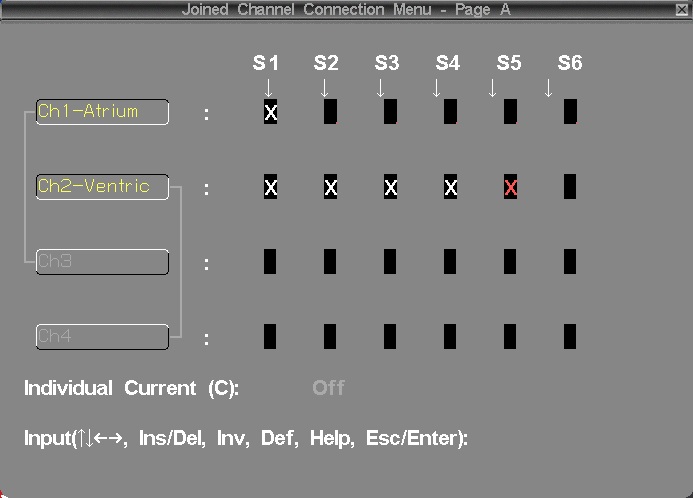
There are alternative, less commonly used protocols, which may be faster, such as Wellens and Morady protocols. Learn about them here:
Drug assisted arrhythmia induction
Many cardiac arrhythmias are sensitive to autonomic state or circulating adrenaline. The most common example of this is supra ventricular tachycardia, which often requires isoprenaline to be given before an arrhythmia can be sustained.
Isoprenaline can be given as bolus doses, or as an IV infusion. It elevates baseline heart rate and decreases refractory periods particularly in the AV node. Isoprenaline infusion is usually administered until the baseline heart rate is elevated to at least 120bpm, or the baseline rate has elevated by at least 25% of the resting value. Diagnostic testing may then be repeated, typically with requiring a faster S1 drive cycle of 400ms to pace the heart.
Patient should be observed closely during isoprenaline infusion, because this drug occasionally may cause a paradoxical vasovagal reflex response, resulting in a tachycardia with profound hypotension.
Atropine can be used in a similar manner to isoprenaline, but is seldom used due to its side effects, prolonged duration of action and lack of reversal agent. It blocks the action of the vagus nerve on the heart. If used together with propranolol, a beta blocker which inhibits the sympathetic autonomic system, the heart can be studied in the absence of external autonomic influences, but this is rarely done clinically.
Following pulmonary vein isolation ablation, pacing manoeuvres are used to confirm the loss of conduction both into and out of the vein. Where conduction block is thought to be temporary, or is unclear, the injection of Adenosine can be used to temporarily augment conduction across the partially effective ablation line, identifying segments of incomplete ablation, which can then be re-ablated to cause permanent block.
3. Measuring tachycardias
Arrhythmia Entrainment
Entrainment is performed because the first returned beat of a tachycardia after entrainment can provide much diagnostic information.
Entrainment of an arrhythmia involves pacing during tachycardia, at a slightly faster cycle length. After pacing is stopped, the last few atrial signals are measured and assessed to ensure that they were accelerated to the paced rate. If they were not, then the tachycardia was not entrained, and the maneuver should be attempted again.
![]() If pacing caused tachycardia termination, then the PPI cannot be assessed, and the tachycardia should be re-induced in order to make a further attempt at entrainment.
If pacing caused tachycardia termination, then the PPI cannot be assessed, and the tachycardia should be re-induced in order to make a further attempt at entrainment.
If you have successfully entrained, then the first beat after you stop the pacing, will be identical in appearance to the intrinsic tachycardia and the same tachycardia (morphology and timing) will then continue as before pacing.
We inspect the first post pacing beat for the following:
- Post Pacing Interval, to tell us if the pacing catheter is in the arrhythmia circuit (and is therefore a good place to ablate). This applies to any re-entrant tachycardia such as VT, SVT and Flutter.
- The pattern of activation of first post pacing beat (E.g.: V-A-V or V-A-V-V, which tells us if SVT is re-entrant or atrial tachycardia.).
Post Pacing Interval (PPI)
Following the entrainment of an arrhythmia, the time taken for the next electrogram to be sensed on the pacing catheter is termed the post pacing interval.
This is used to identify location of the circuit.
The difference between the PPI and the TCL is an indication of the distance of the pacing catheter to the re-entrant circuit (6;7). The PPI must be > TCL (if not entrainment probably did not occur). If the PPI is within 30ms of the TCL, then the pacing catheter is thought to be inside (or very close to) the re-entrant circuit.
![]() To summarize:
To summarize:
-
-
-
- If PPI – TCL >= 0, there will be entrainment
- If PPI – TCL <= 30, the pacing catheter is very close to the circuit
-
-

Resetting
An arrhythmia can be reset by inserting a single stimulus into the excitable gap of a circuit. Entrainment described earlier is an example of repetitive resetting.
There are several conditions to reset a reentrant tachycardia:
- The stimulus must reach the circuit through the entry site or critical isthmus),
- Enter the excitable gap of the circuit (where tissue is excitable)
- Collide with the ongoing tachycardia wavefront
- And propagate through the tachycardia reentrant path (also called by some physician ‘critical isthmus’) to the exit of the circuit.
The exit of the resetting wave should be at an earlier than the tachycardia time (accelerate the tachycardia) and, in most of the cases, capture the tachycardia circuit at that pace.
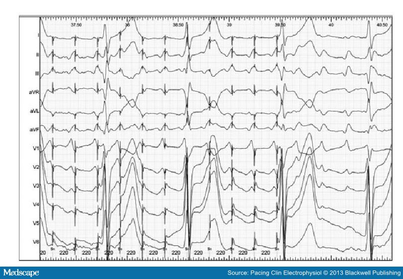
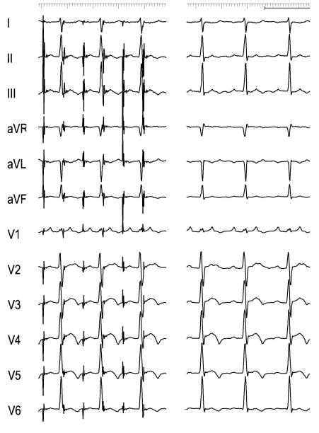
![]() Resetting with Fusion: When resetting is successful and a change in the morphology of the tachycardia complex is observed on surface ECG or intracardiac electrograms, that is called “fusion”. In the electrograms can be observed the progressive advancement of the entrainment and how the pattern changes from the natural tachycardia complex to the stimulated tachycardia complex.
Resetting with Fusion: When resetting is successful and a change in the morphology of the tachycardia complex is observed on surface ECG or intracardiac electrograms, that is called “fusion”. In the electrograms can be observed the progressive advancement of the entrainment and how the pattern changes from the natural tachycardia complex to the stimulated tachycardia complex.
Below [Pic 1], we can see an example of entrainment with fucion in a 12 ECG electrogram.
Termination
Many times the termination of the tachycardia occurs during the attempts of entrainment.
Termination could be happen when the extrastimulus collides with the tachycardia impulse that is already in the reentrant circuit. Following the example of the previous section, the extrastimulus finds refractory period tissue antidromically and clashes orthodormically with the tachycardia wavefront terminating the arrhythmia.
If this is the case, some information can still be deduced based on how termination occurred.
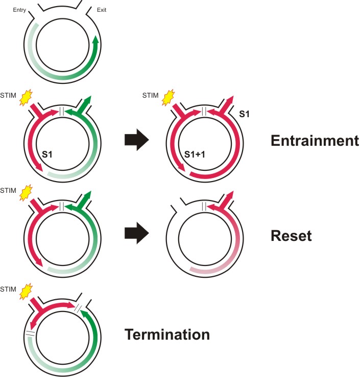
Above, you can find a little brief of the entrainment phenomenon.
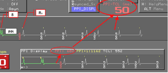
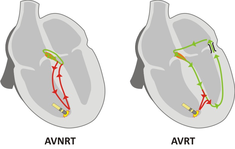
SVT, an illustrated example of Entrainment pacingUsing an S1 protocol, pacing is delivered to the RVA at 20ms faster than TCL. The PPI interval Then, if the tachycardia was successfully entrained, the time interval from the final S1 until the onset of the first sensed beat on the RVA is measured. This is the PPI. This value can be compared with the smaller value TCL. As shown in the figure on the right, the PPI is approximately equivalent to the TCL (green) PLUS the time taken for the pacing impulse to get from the RVA to the circuit and back again (red). We can see that the PPI minus TCL is much longer for AVNRT than for AVRT, as the circuit is further away. As a general rule, if the PPI is >115ms longer than the tachycardia cycle length, then the tachycardia is more likely to be AVNRT than AVRT. The TCL is determined by the green path, although the length of the path does not dictate the TCL, as the AVNRT path contains a slow AVN pathway which determines most of the cycle length. Above, graphic representation of AVNRT (left) and AVRT (right).
However, when entraining a tachycardia, the tachycardia must by definition be temporarily accelerated. This can lead to prolongation of conduction over the AVN due its decremental properties. Therefore in borderline cases, or where doubt exists, the corrected post pacing (cPPI) interval should be assessed. Here, the AH time prior to the entrainment is measured, and the AH time measured on the last beat of entrainment. Any increase in the value is subtracted from the measured PPI to give a cPPI. A cPPI-TCL of >110ms is highly suggestive of AVNRT.
The pattern of response The pattern of response following the last paced beat can also provide useful information. Following the final paced V signal, if the order of the following electrograms is “A-V”, then the diagnosis is either AVNRT or AVRT. If the order is “A-A-V”, then the diagnosis is atrial tachycardia.
The transition zone It is important to ensure that the first paced beat is synchronized to the tachycardia, and that ventricular pacing gradually fuses with the tachycardia. When this occurs, the timing of the first accelerated atrial electrogram may indicate the presence of a concealed accessory pathway. During the onset of entrainment, the surface ECG morphology gradually changes from the narrow complex tachycardia to that of a paced complex. The time over which this change takes place is termed the transition zone. [Ref 2] If the atrial electrogram accelerates from TCL to the paced rate during the transition zone, an accessory pathway must be present. Why? Because of fusion to have occurred, the pacing must have fused with impulses traveling down the His bundle. Therefore retrograde atrial acceleration must have occurred by another route. If atrial advancement occurs following the stabilization of a purely paced complex morphology (after transition zone), then advancement probably occurred over the retrograde AV node.
Termination When ventricular pacing terminates an SVT, the mechanism of termination can assist in diagnosis of the tachycardia. If the atrial rate was not affected by pacing, atrial tachycardia is excluded, as a premature atrial event would have been needed to terminate the SVT. An accessory pathway is also unlikely as the pathway would usually conduct from the V to the A. |
A more specific example of how to diagnose using entrainment? Click below.

Pace mapping
Pace mapping is a method of locating the source of ventricular activation, commonly used during ventricular tachycardia ablation. The technique requires a sample of the tachycardia or ectopic beat to have been recorded during the current clinical case, this will be the “template” (Note: old ECGs are not usually suitable due to variability in ECG electrode positioning).
With the recording “template” in a separate review window, the ablation catheter is paced using an S1 protocol at a low current. The resulting QRS complex is then compared to the template. If the resulting complex is identical to the template in all 12 leads, then the catheter is said to be at the origin of the clinical activation (breakout), but if not the ablation catheter is moved, and pacing repeated until an exact match is found.
If you are matching an ectopic, you can pace S1 quite slowly, say at 600ms, but if you are matching a VT, you need to pace at close to the VT cycle length, as pacing at slower rates can give subtly different morphology even when paced at the exact source.
Example of atrial tachycardia pacemapping. Atrial pacing (right) to emulate the P waveform of the tachycardia (left) that it is used as a template. [Pic 2]
4. Terminating arrhythmias
Re-entrant Arrhythmia termination
Termination of arrhythmias by pacing aims to capture part of the circuit during it excitable phase, and render it refractory to the tachycardia wavefront.
Method 1: Overdrive burst pace (also valid for triggered arrhythmias)
Burst pacing is similar to standard pacing, but implies a rapid short lived period of pacing in S1. It delivers S1 pacing at specified cycle length. Usually only 5-10 seconds of pacing is required. Rarely up to 30 seconds of pacing may be needed (e.g. to overdrive atrial flutter).
Overdrive pacing requires an S1 pacing train delivered at faster rate than the TCL (normally it is used the formula 90% TCL, which usually means 50ms or faster), for about 10 beats. As this may transiently entrain the tachycardia, it may allow continuation of the tachycardia, so multiple attempts may be required.
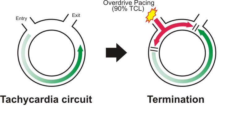
Above, Overdrive suppression phenomenon in re-entrant tachycardias.

Method 2: Underdrive pace
Underdrive pacing uses a fixed S1 train significantly slower than the tachycardia, so must be delivered in asynchronous mode (A00 or V00), and relies on the chance delivery of an asynchronous pacing beat into an excitable gap in the tachycardia, which then interrupts the tachycardia.
There is a potential risk that due to pacing into the tachycardia, that pacing may occur on a vulnerable part of the T wave and VF be induced. However in a highly monitored environment such as an EP lab, this risk is very small.

![]() A very interesting article: "Underdrive pacing to terminate ventricular tachycardia" by Richard Bond, Paul W X Foley, Yaver Bashir.
A very interesting article: "Underdrive pacing to terminate ventricular tachycardia" by Richard Bond, Paul W X Foley, Yaver Bashir.
Method 3: Sensed extras – single or multiple
Single Extra stimuli can also be used to render part of the tachycardia circuit refractory, similar to underdrive pacing, but uses synchronised impulses.
The initial impulse should be delivered just shorter than the TCL, and then progressively shortened or “scanned” until the tachycardia terminates (or extra-stimulus becomes refractory). Once successfully terminated, a single extra-stimulus to the same site at the same coupling interval can then be used to rapidly terminate the same tachycardia without the need for “scanning extras”.
Decremental pacing during SVT
This is not frequently used. If during an antegrade study, an SVT is initiated, once adequate pacing maneuvers have been performed to identify the tachycardia, rather than burst pacing to terminate the tachycardia, an AV wenckebach test can be performed, starting at TCL, and terminating when AV block occurs in the usual manner. This can save the need to start an AVW test from sinus cycle lengths.
5. Specialized pacing protocols
Zipes test: AVJRT versus AVNRT
Ablation in the slow pathway area commonly results in junctional beats, and these are markers of effective ablation. However, these may be persistent following the end of ablation, or may be triggered by the use of isoprenaline. This can result in a tachycardia which is similar in appearance to the initial AVNRT, but is in fact an automatic junctional tachycardia (at 130-140bpm, for which no further treatment is required).
Two diagnostic tests can be used to differentiate the two tachycardias.
The first has to be described [Ref 1] uses atrial extra stimuli delivered during the tachycardia, scanned progressively earlier over a range of intervals, until His coincident, and then earlier. (This has been explained previously in the Section “Arrhythmia Entrainment”)
If a His coincident atrial extra stimulus perturbs the timing of the following His signal, then the diagnosis is AVNRT as the junction could not have been affected (his coincident / refractory).
If the atrial extra results in advancement of the immediate His, and the tachycardia continues, the diagnosis is Junctional Tachycardia (in AVNRT the retrograde fast pathway would have been blocked causing termination).
The second test is called His-synchronous PVC (or Zipes test). During a tachycardia a synchronized ventricle extra stimuli will be delivered. The timing of the extrastimulus that is delivered is critical, and should be synchronized with the tachycardia. Single extra beats are introduced to capture the right ventricle, intended to occur at exactly the same time as the His signal seen on the His catheter.
By `scanning` earlier with successive 10ms decrements, the extra is delivered 20-30ms earlier than the observed His signal, then the earliest atrial signal following the PVC is monitored for any 'perturbation' in timing.
In AVNRT the ventricular extra stimulus should never alter the atrial activation time as the route up to the atrium is blocked by the His which has been depolarized, in contrast to AVRT where there is another route up to the atrium [Ref 2].

Differential atrial pacing after Flutter ablation
A very good example of differential pacing is performed after an atrial flutter ablation to demonstrate completeness of block of re-entrant pathway. It involves pacing at different distances away from the ablation line along the Cavo-tricuspid isthmus (CTI). The physician will observe if the activation of the other side of the ablation line has occurred across the ablation or by going around the atrium (slow conduction versus block).
Pacing is required from 4 different sites on the tricuspid annulus, and conduction times compared to ensure that the impulse does not travel through the CTI.
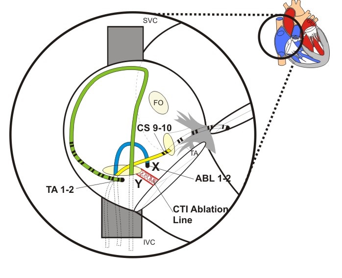
Figure above shows a view of the Right atrium with diagnostic catheter at the lateral RA wall, a CS and an ablation catheters. The Isthmus Ablation Line has been performed between the Inferior Vena Cava and the Tricuspid Annulus.
The exact procedure may be found accessing here:

Para-Hissian pacing
This test can reveal the existence of a concealed pathway, but it does not show that the pathway is part of a circuit, nor responsible for palpitations or tachycardia.
The test is always performed in sinus rhythm [Ref 3]. The His catheter is used for pacing from the distal electrodes. Pacing at maximum output aims to capture the His bundle. This results in a surface ECG which appears similar to the normal QRS (that means relatively narrow). The resultant atrial activation is observed (Stim-A time). The pacing output is then decreased until His bundle capture is lost, and the QRS becomes wider. The atrial activation is re-assessed.
Normal conduction results in a prolongation of the stim-A time with the transition from narrow complex capture to wide complex capture. Where there is no change in Stim-A time, a para‑hissian pathway is present. Ensure that direct atrial capture does not occur, as this is often seen when pacing from the His catheter.
|
|
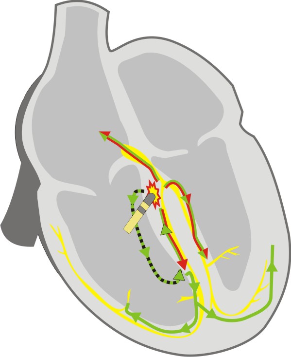
Normal Physiology During His bundle capture the atrium is activated by direct conduction from His to AV node. After loss of His bundle capture, myocardial capture and conduction spreads down the interventricular septum to enter the Purkinje fibres, and travel back up the bundle branches to the His bundle and AV node. The increase in distance covered by the paced beat results in an increase in the Stim to Atrial activation time Red - Conduction Path with High Output pacing (Hisian capture) Green - Conduction path with Low output pacing (ventricular capture) |
|
|
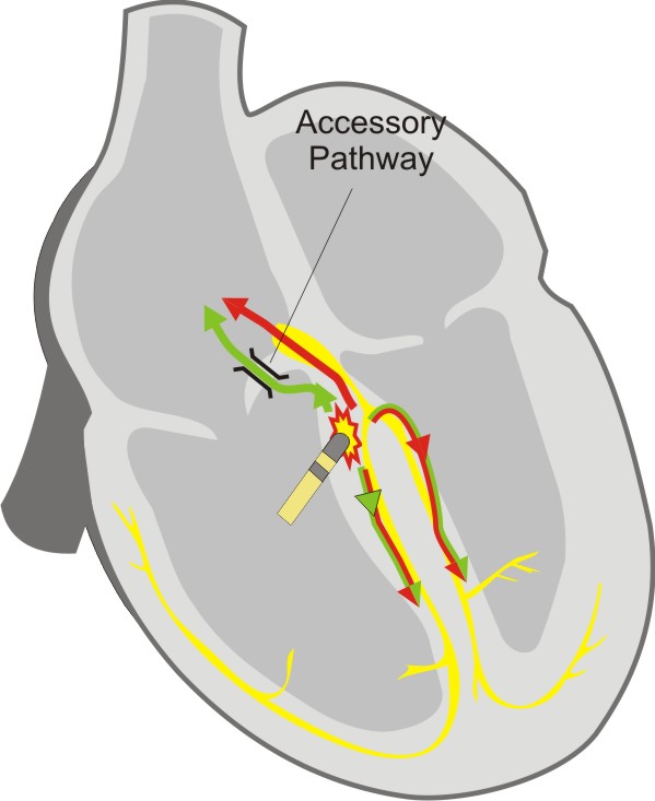
Septal accessory pathway During His bundle capture, the atrium is activated via the accessory pathway, which appears similar to the AV node. After loss of His bundle capture denoted by widening of the QRS, the atrium continues to be activated by the accessory pathway, and the Stim to Atrial time remains unchanged as there has been no requirement of the Purkinje fibres or His bundle to excite the atrium. Red - Conduction Path with High Output pacing (Hissian capture) Green - Conduction path with Low output pacing (Ventricular capture) |
It is important that when pacing the His bundle at high output, that the atrium is not simultaneously captured.

Oesophageal pacing
Transesophageal atrial pacing is possible because of the proximity between the oesophagus and the posterior aspect of the atria. This technique is non-invasive, therefore there is no need to bring the patient to the cathlab, This method has been mainly tested in patients with a history of spontaneous supraventricular tachycardia (SVT).
Bipolar or unipolar recordings can be made, but obviously the strengh-duration curve of esophageal pacing is different than that of endocardial pacing. Acording to some studies, lowest thresholds can be reached at pulse widths between 10 and 20 msec and 5-15mA.
In order to minimize the patient discomfort, the studies have tried to use lower pacing thresholds using a bipolar electrode with wide interelectrode distance. [Ref 4]
In conclusion, using a rapid atrial pacing from the esophagus can be used to induce and terminate SVT for diagnostic or therapeutic purposes; and that esophageal pacing provides a convenient way to assess repeatedly the efficacy of long-term drug therapy and to screen patients for preexcitation syndromes. [Ref 5]
However, a few limitations to the technique have been found:
a) there is only one site of atrial pacing and recording,
b) there is no ventricular pacing and
c) sometimes atrial capture can be difficult to assess on the surface ECG during premature extrastimuli delivery.
References:(Ref 1) Padanilam BJ, Manfredi JA, Steinberg LA, Olson JA, Fogel RI, Prystowsky EN. Differentiating junctional tachycardia and atrioventricular node re-entry tachycardia based on response to atrial extrastimulus pacing. J Am Coll Cardiol 2008;52:1711-7.(Ref 2) Zipes DP, DeJoseph RL, Rothbaum DA. Unusual properties of accessory pathways. Circulation 1974;49:1200-11.(Ref 3) Hirao K, Otomo K, Wang X et al. Para-Hisian pacing. A new method for differentiating retrograde conduction over an accessory AV pathway from conduction over the AV node. Circulation 1996;94:1027-35.(Ref 4) Thierry Verbeet MD, José Castro MD, Pierre Decoodt MD. Transesophageal pacing : a versatile diagnostic and therapeutic tool. Department of Cardiology, University Hospital Brugmann, Brussels, Belgium.(Ref 5) J J Gallagher, W M Smith, C R Kerr, J Kasell, L Cook, M Reiter, R Sterba and M Harte. Esophageal pacing: a diagnostic and therapeutic tool.
6. Synchronizing pacing
During this course we have talked extensively about the importance of synchronizing pacing: having a good sensing signal, matching the pacing protocol with the type of synchronization and knowing the parameters related with synchronization of your cardiac stimulator.
Delay first S1
Delivering a S1 train without no synchronization may cause the first few S1 stimuli to not capture, delaying start of stimulation and adding a small risk of stimulating the heart in the vulnerable period causing VF.
Having this type of synchronization enabled and no ECG signal may hold stimulation off indefinitely. During an emergency, it has happened that urgent pacing was commenced, but no stimulation occurred due to this hold off. Advanced stimulators include a fail-safe timeout, so pacing starts after several; seconds regardless of ECG.
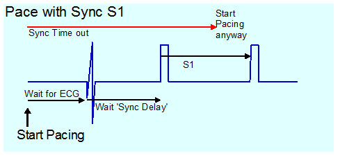
![]() Warning! Some stimulators have no timeout and in this mode, absence of ECG sensing leads to absence of pacing.
Warning! Some stimulators have no timeout and in this mode, absence of ECG sensing leads to absence of pacing.

Demand S1 pacing
This is similar to inhibited mode pacing used in “VVI” pacing. With pacing mode set to demand, S1 pacing will only be delivered if the S1 cycle length is shorter than the cycle length on the sensed channel.
This is not frequently needed. If mapping an AVRT pathway during tachycardia, breaking the tachycardia by ablating the pathway will result in sudden change of heart rate (from SVT to sinus), which will be accompanied by a large movement of the heart which will commonly displace the catheter). This results in a partially effective ablation, which results in a poor outcome as the pathway may be stunned but recover at a later time. Further mapping of a “stunned” pathway may not be possible.
If demand S1 pacing is used 20ms longer than the TCL, as soon as the pathway is interrupted, ventricular pacing is delivered slightly slower than the original tachycardia, with no significant movement of heart or catheter.
Some other use may be as well in VT Induction, for this S1 has to be adjusted for starting when ectopic beats occurs.
Another use could be during the ablation of AV Node. In this case it is required to start pacing automatically on AV block.